Hot Standby Router Protocol configuration on cisco router.
HSRP Configuration Lab in Cisco packet tracer.
In this article I will explain you what is HSRP (Hot Standby Router Protocol) and how to configure and use it. I will explain all HSRP Commands along with HSRP Metrics and Configuration in few simple steps.
HSRP is actually a FHRP (First Hop Redundancy Protocol). FHRP(First Hop Redundancy Protocol) means it will allow you to configure more than one physical router such that it will act as a single router.
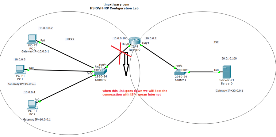
Why We need HSRP or FHRP?
In above image you can see if a single port of router gets down the complete network get disconnected from ISP. Or in other word you can say that if any port goes down,then whole LAN will be disconnected from internet. And to avoid such incidence we need REDUNDANCY which we can achieve through 3 different protocols and they are:

1.HSRP
2.VRRP
3.GLBP
Remember these protocols will work on Layer 3 switches to along with Routers.
It means we can configure all above three protocols on router as well as layer 3 switches.
But this particular article is dedicated to HSRP(Hot Standby Routing Protocol).So here i will discuss on HSRP working and configuration only.In some other articles I will discuss about VRRP and GLBP.
Roles of Routers in HSRP Configuration.
Active Router: Active Router is actually that router which is presently working as a gateway.
Standby Router: Standby Router are backup of Active Router, and will come in function when active router is down.
Listening Router: All the routers that participate in HSRP including active router and Standby router are known Listening router.
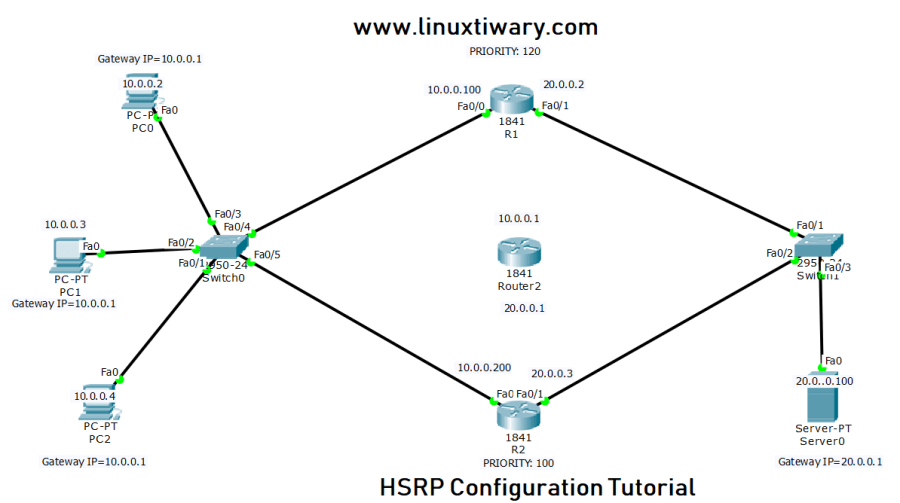
Step 1:Draw the HSRP Topology Diagram in Cisco Packet Tracer.
Here I have used Cisco Packet Tracer Software to design the HSRP LAB Topology to make you understand HSRP.
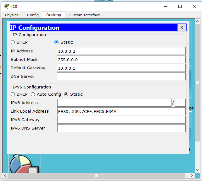
Step2: Assign the IP Address to PC and Server with Gateway IP .
Assign IP Address to all PC and Server as I have mentioned in above topology diagram with mentioned gateway IP.
I have show you one example in below image and i hope it will help you to assign ip address and default gateway.

Step 3: Important Points to be kept in Mind During HSRP Configuration.
We can only have one and only one Active Router in HSRP.
We can only have one and only one Standby Router in HSRP.
Selection of Active and Standby Router will be done on the basis of PRIORITY.
The Range of PRIORITY will be from 0-255.
The Default Value of PRIORITY is 100.
The Router with Highest PRIORITY will be elected as Primary and the Router with second PRIORITY will be act as BACKUP Router.
IF By chance or anyway two routers have same PRIORITY in that case the HIGHEST IP ADDRESS on the HSRP’s Interfaces gets elected as Active Router.
Step 4: Virtual Router Role in HSRP.
Remember the Virtual router has it’s own IP and MAC Address.
The virtual IP Address will be default gateway of all host.
Every time a host sends a ARP Request Virtual MAC Address is Returned.
Hosts machine have no idea which router actually working for forwarding traffic.
By saying Virtual IP Address you don’t understand there will be no such IP. IN HSRP virtual ip address is a normal ip address which we can assign as the VIP.
Step 5: HSRP configuration on Router R1:
R1(config)#int fa0/0 R1(config-if)#standby 11 ip 10.0.0.1 R1(config-if)#standby 11 priority 120
Step 6: HSRP configuration on Router R2:
R2(config)#int fa0/0 R2(config-if)#standby 11 ip 10.0.0.1 R2(config-if)#standby 11 priority 100
Step 7: Description of code used in Step5 and Step6 during HSRP Configuration.
Standby 11 here specifies the group to which interface belongs in HSRP.
As we know the Default PRIORITY is 100 but we have changed the PRIORITY of Router R1 to 120.
and PRIORITY or R2 is 100(Which is by default and hence have lowest PRIORITY than R1)
Step 8: Result Comes out from HSRP Configuration in Step5 and Step 6
As we can see in above HSRP Configuration Router R1 has highest PRIORITY than Router R2
So according to our configuration here Router R1 will work as Active Router and R2 will be Backup Router.
Step 10: Verify the HSRP Configuration using below commands.
Verification of HSRP Configuration on Router R1:
R1#show standby brief P indicates configured to preempt. | Interface Grp Pri P State Active Standby Virtual IP Fa0/0 11 120 Active local unknown 10.0.0.1
R1#show standby FastEthernet0/0 - Group 11 (version 2) State is Active 6 state changes, last state change 00:11:38 Virtual IP address is 10.0.0.1 Active virtual MAC address is 0000.0C9F.F00B Local virtual MAC address is 0000.0C9F.F00B (v2 default) Hello time 3 sec, hold time 10 sec Next hello sent in 0.967 secs Preemption disabled Active router is local Standby router is unknown Priority 120 (configured 120) Group name is hsrp-Fa0/0-11 (default)
Verification of HSRP Configuration on Router R2:
R2#show standby brief P indicates configured to preempt. | Interface Grp Pri P State Active Standby Virtual IP Fa0/0 11 100 Standby 10.0.0.100 local 10.0.0.1
R2#show standby FastEthernet0/0 - Group 11 (version 2) State is Standby 3 state changes, last state change 00:16:09 Virtual IP address is 10.0.0.1 Active virtual MAC address is 0000.0C9F.F00B Local virtual MAC address is 0000.0C9F.F00B (v2 default) Hello time 3 sec, hold time 10 sec Next hello sent in 0.432 secs Preemption disabled Active router is 10.0.0.100 Standby router is local Priority 100 (default 100) Group name is hsrp-Fa0/0-11 (default)
Step 11: Now Similarly Configuration HSRP on Bothe Router R1 and R2 on Other Side of Router.
Now I am goint to configure HSRP on Other Interface of Router. say Fa0/1 here.
HSRP Configuration on R1 Fa0/1 Interface:
R1(config)#int fa0/1 R1(config-if)#standby 12 ip 20.0.0.1 R1(config-if)#standby 12 priority 120
HSRP Configuration on R2 Fa0/1 Interface:
R2(config)#int fa0/1 R2(config-if)#standby 12 ip 20.0.0.1 R2(config-if)#standby 12 priority 100
Step 12: Again a Final Verification of HSRP Configuration on Both Routers.
Final HSRP Verification on Router R1:
R1#show standby brief P indicates configured to preempt. | Interface Grp Pri P State Active Standby Virtual IP Fa0/0 11 120 Active local 10.0.0.200 10.0.0.1 Fa0/1 12 120 Active local 20.0.0.3 20.0.0.1
R1#show standby FastEthernet0/0 - Group 11 (version 2) State is Active 6 state changes, last state change 00:11:38 Virtual IP address is 10.0.0.1 Active virtual MAC address is 0000.0C9F.F00B Local virtual MAC address is 0000.0C9F.F00B (v2 default) Hello time 3 sec, hold time 10 sec Next hello sent in 1.988 secs Preemption disabled Active router is local Standby router is 10.0.0.200 Priority 120 (configured 120) Group name is hsrp-Fa0/0-11 (default) FastEthernet0/1 - Group 12 (version 2) State is Active 4 state changes, last state change 00:22:56 Virtual IP address is 20.0.0.1 Active virtual MAC address is 0000.0C9F.F00C Local virtual MAC address is 0000.0C9F.F00C (v2 default) Hello time 3 sec, hold time 10 sec Next hello sent in 0.155 secs Preemption disabled Active router is local Standby router is 20.0.0.3 Priority 120 (configured 120) Group name is hsrp-Fa0/1-12 (default)
Final HSRP Verification on Router R2:
R2#show standby brief P indicates configured to preempt. | Interface Grp Pri P State Active Standby Virtual IP Fa0/0 11 100 Standby 10.0.0.100 local 10.0.0.1 Fa0/1 12 100 Standby 20.0.0.2 local 20.0.0.1
R2#show standby FastEthernet0/0 - Group 11 (version 2) State is Standby 3 state changes, last state change 00:16:09 Virtual IP address is 10.0.0.1 Active virtual MAC address is 0000.0C9F.F00B Local virtual MAC address is 0000.0C9F.F00B (v2 default) Hello time 3 sec, hold time 10 sec Next hello sent in 1.256 secs Preemption disabled Active router is 10.0.0.100 Standby router is local Priority 100 (default 100) Group name is hsrp-Fa0/0-11 (default) FastEthernet0/1 - Group 12 (version 2) State is Standby 3 state changes, last state change 00:24:36 Virtual IP address is 20.0.0.1 Active virtual MAC address is 0000.0C9F.F00C Local virtual MAC address is 0000.0C9F.F00C (v2 default) Hello time 3 sec, hold time 10 sec Next hello sent in 2.718 secs Preemption disabled Active router is 20.0.0.2 Standby router is local Priority 100 (default 100) Group name is hsrp-Fa0/1-12 (default)
Step 13: Communication Testing Between ISP server and Clients PC.
PC>tracert 20.0.0.100 Tracing route to 20.0.0.100 over a maximum of 30 hops: 1 1 ms 0 ms 0 ms 10.0.0.100 2 0 ms 0 ms 0 ms 20.0.0.100 Trace complete.
http://www.youtube.com/watch?v=J7QH_d6ZM-E
Discover more from Learn Linux CCNA CCNP CEH CISSP CISA Penetration-Testing Bug Bounty IPv6 Cyber-Security Network-Security Online
Subscribe to get the latest posts sent to your email.
